Easy DC power supply efficiency measurements
January 28, 2021
Introduction
Many electronic designs require a power supply that delivers a known voltage over a specific range of current loads and conditions. In many instances, the efficiency of the supply is an essential characteristic of the design. More efficient designs covert the input power into a higher percentage of output power than less efficient designs. Since the majority of power supply losses are generated as heat within the supply, more efficient designs tend to run cooler, offer higher stability, and longer operating lifetime. More efficiency often just makes more sense. This is especially important for applications that require battery power like remote IOT sensing or communications modules that need to be operational for an extended length of time.
In order to make more efficient designs, we need to know how to measure power supply efficiency. In this note, we will introduce the basic theory for DC power supply efficiency calculations, present a physical setup for accurately measuring the important parameters, and provide an example program that coordinates measurements and automatically calculates power supply efficiency quickly.
Background Theory
The efficiency of a power supply is simply the ratio of the power out vs the power in.
From power electronics theory:
η = Pout / Pin
Where η = Power Efficency, Pout = Output power (Watts), and Pin = Input power (Watts)
For DC power,
P = V * I
Where P = Power (Watts = Joules/s), V = Volts (Joules/Coulomb), and I = Current (Amps = Coulombs/s)
So, if we measure the input voltage and current draw, we can calculate the input power.
Pin = Vin * Iin
If we measure the output voltage and current draw, we can calculate the output power.
Pout = Vout * Iout
Now, some simple division provides Power Efficiency as a ratio which can be easily shown as a percentage at that specific load value. A curve of the efficiency vs. load values can be calculated by stepping the load value and calculating the efficiency at each load value and plotting it as shown below:
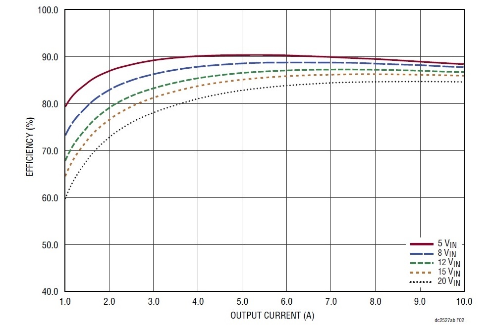
Figure 1: Sample Power Supply Efficiency Curve, from Linear Technologies Datasheet for an LTM4646.
Setup
The most basic setup for this test uses:
Qty 1 Power Supply
Qty 1 DC electronic load
Typically wired as shown:
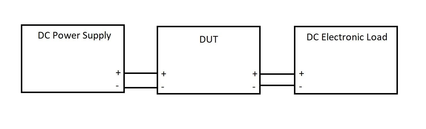
The process:
- Supply power to the DUT
- Set the load for a given current draw
- Measure the Vin, Iin, Vout, and Iout at the load current set point
This is about as simple as it gets with an electronics test.. but there are two important considerations with this setup:
-
- How many load steps are required to accurately build an efficiency curve for your DUT?
- What level of resolution and accuracy do you need for the calculation?
Typical power efficiency curves require 10 or more load current steps to get an accurate representation of efficiency. Manually performing this test can be a bit tedious and prone to error. To save time, you may want to consider automating the setup with a computer. Here is an example we built using Python that may be helpful: LINK TO EXAMPLE
For the resolution question, consider that most commercial power supplies and DC loads have 3.5 digit measurement resolution and accuracy values that may not be high enough to characterize the DUT confidently.
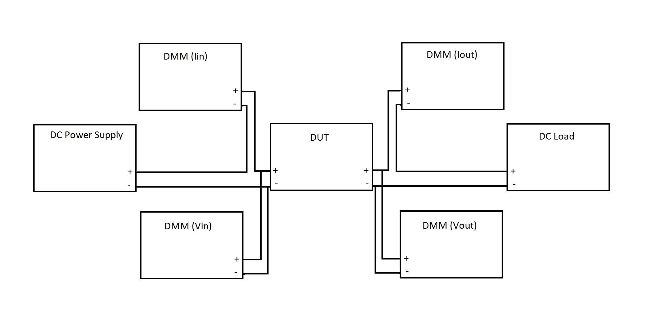
To address these two considerations, we added four multimeters: One to measure Vin, Iin, Vout, and Iout and created a computer program to automate the instrument configurations, step load current values, and data collection.
Here is a wiring diagram of the setup:
Here is a picture of the experimental setup which uses a SIGLENT SPD1168X, SDM3055s for Iin and Iout, SDM3045Xs for Vin and Vout, and an SDL1020X-E DC load:
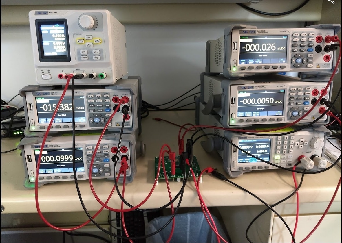
Here the DUT is the Linear Technologies LTM4646 power module we used in this video on Load Step Testing
NOTE: Keep the leads to the load as short as possible to minimize I*R voltage drop and select DMMs with a low voltage burden on the current measurement ranges you expect to use. Long leads and a high voltage burden can cause the DUT to reach its output voltage limit before reaching the maximum expected current draw.
Summary
Power supply efficiency is an important aspect of any power supply design. Using a few standard pieces of test gear, one can quickly build a modular system with enough resolution to measure the most demanding applications.