AWG Basics-1
April 23, 2020
Many electronic designs feature the ability to monitor or measure input signals and then perform another task or function based on that input signal. A simple example could be a circuit that looks for an input voltage to exceed a specific amount and triggers another action after it occurs. In such cases, having the ability to configure and deliver a known or simulated signal can be a critical addition to testing the performance of the design. Unlike acquisition instruments that measure a signal, an input signal can be created using a signal source. This can be as simple as a DC power supply or as complex as a digital communication signal delivered by an RF Vector Source. One of the most flexible and useful signal sources available today is the Arbitrary Waveform Generator (AWG).
In this series of notes, we are going to introduce some of the features that make AWGs so useful and explain in a bit more detail just how they work.
What types of signal sources are on the market today?
Let’s start with the basics. Most sources can be divided into two broad application categories: Digital and Analog.
Signal sources specially created for digital applications are often called logic sources. Logic sources can be roughly divided into two categories: Pulse and pattern generators. A pulse generator can output square waves and pulse streams. The output frequency of the pulse generator is generally very high and it is often used to test digital devices. A pattern generator, also known as a logic source or data generator is a bit unique. This kind of instrument generally has 8 or 16 output channels, but higher channel counts are available. Each output can generate various types of synchronous digital pulse streams, generally from a low to a high voltage value, 0-5 V for example. Pattern generators are often used as excitation signals for computer buses, digital telecommunications units, and other serial communications links.
Analog generators typically have one or two outputs and feature a wider array of possible output levels, wave shapes, and frequencies than digital sources. More specialized forms of analog generators also exist for high frequency applications. We aren’t going in to further detail about them here, but some common types include RF signal generators, microwave signal generators, and baseband signal generators.
In this article, we will concentrate on the most general purpose signal source, the arbitrary waveform generator. In simple terms, an arbitrary waveform generator is a device that creates an output signal based on a digital waveform file, created from a series of discrete output sample points, and “plays” the file contents at the source output of the generator. Using this sampling principle, waveforms of almost any type can be created, including basic waveform functions like square, sine, and ramping output shapes.
Arbitrary waveform generators can also have more advanced functions like output triggering and system clock signals for synchronizing external instruments. One such generator is the SIGLENT SDG2000X series function / arbitrary waveform generator shown in Figure 1 below.
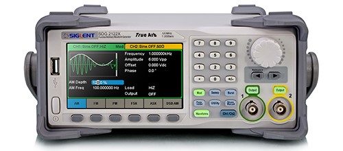
Figure 1: SIGLENT SDG2000X function / arbitrary waveform generator
What is the waveform generator used for?
As mentioned previously, most arbitrary waveform generators include basic function types like sine, square, and triangle waves. In addition, waveform generators can also generate analog and digital modulation signals, supporting the output of linear / logarithmic sweep signals and pulse trains. Many of SIGLENTs SDG series of generators support AM, FM, PM, FSK, ASK, DSB-AM and other analog and digital modulation functions and include a large standard library of included arbitrary waveform functions.
There are hundreds of applications for waveform generators, but in the field of electronic test and measurement, the application range can be basically divided into three types: inspection, verification, and limit / margin test. During the commissioning phase of a design, the engineer needs to test the parameters of the product to verify whether the product meets the relevant design specifications. In this process, the waveform generator can be used to source the signal specified in the design specification. Here, the Engineer can observe the response of the design, compare the results with the specifications, and perform any adjustments that may be necessary with the design. In addition, newly developed industrial control modules, data conditioning modules, and others all need to use waveform generators to test their linearity and monotonicity through exhaustive testing. In many occasions, the waveform source needs to add a known, repeatable distortion in quantity and type to the signal it provides. With many generators, you can add noise and programmed distortion to the signal and directly test the ability of the design to handle specific real-world signal issues.
What are the main indicators of the waveform generator? What do these indicators mean?
Oscilloscopes have common banner specifications: Bandwidth, memory depth, and sampling rate. When we select a suitable oscilloscope, these three major indicators are often our first consideration.
Does the waveform generator also have the so-called three major indicators? The answer is yes. In the category of waveform generators, there are also concepts of bandwidth, sampling rate and memory depth.
- Bandwidth
The bandwidth of the waveform generator is often defined as the maximum frequency of a sine wave. Unfortunately, what applies for a sine wave may not apply to other waveform types. For example, the maximum sine wave output frequency of the SIGLENT SDG2122X is 120 MHz, while the square wave has a maximum frequency of 25 MHz. The reason for this difference is that a square waveform transitions very quickly from one voltage value to another. Faster transitions require that the waveform contains many higher-frequency components than the smooth transitioning sine wave. In order to avoid heavy distortion of the rising edge of the square wave output, when the waveform generator outputs a square wave, its bandwidth range must be able to include these higher harmonic components.
- Sampling rate
The sampling rate of the waveform generator is usually expressed in mega-samples (MSa/s) or giga-samples per second (GSa/s). For example, the nominal sampling rate of SDG2000X series function / arbitrary waveform generator is 1.2 GSa / s. This parameter indicates the output rate of each sample of the waveform being sourced. The Nyquist sampling theorem stipulates that the sampling rate or clock rate must be at least twice the highest spectral component of the generated signal, thus, accurate reproduction of the original signal can be guaranteed. But in practical applications, twice is often not enough, depending on the type of signal and the rise time. Higher output sampling rates indicate that a signal source is capable of sourcing samples quickly. Low sample rates can limit a generators ability to accurately source a given waveform type.
Here is a quick example.
If you have a waveform made of 1,000 samples and your generator can source 10 MSa/s, the maximum output frequency of the waveform can be calculated as follows:
Frequency = Sample Rate/Samples = 10 MSa/s / 1000 Samples = 10 kHz.
So, the sample rate and number of samples used to create your waveform determine the output waveform period and can be a quick test to determine if the generator will work for your application.
- Memory depth
Memory depth refers to the number of data points used to record the waveform, which determines the maximum number of samples of the waveform data. The bandwidth of the waveform generator is determined by the sampling rate and memory depth. The SDG2000X series function / arbitrary waveform generator supports “point-by-point output”, which can output 8 pts ~ 8 Mpts at a variable sampling rate of 1 uSa / s ~ 75 MSa / s without losing waveform details. Deeper memory provides higher resolution in the time domain and enables users to create more detailed waveforms.
In addition to the above three indicators, frequency resolution and vertical resolution are also important indicators of waveform generators. Vertical resolution refers to the smallest voltage increment that can be programmed in the waveform generator, and is related to the number of DAC bits used in the hardware circuit. It is generally expressed in units of “bits”, which determines the amplitude accuracy of the output waveform. Frequency resolution, the smallest adjustable frequency resolution, that is, the smallest time increment that can be used when creating a waveform, is related to the highest rate of the clock and the conversion rate of the DAC.
The waveform generator is one of the most widely used basic general-purpose instruments and it is an indispensable tool for simulating signals and testing your design performance. For more information, search out our additional articles to give you more understanding of the principles of the waveform generator.