Multi generator synchronization
August 7, 2023
1. Introduction
Multi-channel function generators are useful in many situations. For example, in some testing the generator needs to output several phase-coherent signals and for the phase to be independently adjustable for each signal. In 3-phase power line harmonic distortion testing, a 4 channel generator is required to simulate the multiple voltages and currents.
1.1 Problem
A standalone multi-channel generator can be very expensive.
1.2 Solution
Siglent provides the Multi-Device Synchronization function in the SDG2000X and SDG6000X generators. This allows synchronization among several units in order to output signals with adjustable steady phase relationships. Thus saving on cost.
2. Setup of Synchronization
2.1 Wiring
Multi-Device Synchronization will require the use of the Aux In/Out and 10 MHz In/Out rear-panel interfaces to implement the synchronization. First, all the generators’ Aux In/Out BNC connectors need to be connected together. Next, connect the Master unit’s 10 MHz Out to the Slave unit’s 10 MHz In. Please note that the SDG6000X family has separate 10 MHz In/Out outputs, so more than two units can be synchronized. The wiring interconnection concept is shown in Figure 1.
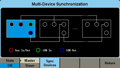
Figure 1. Wiring concept
However, the SDG2000X series’ 10 MHz In/Out ports shares one connector. Therefore, only two units can be synchronized together or they must be the last Slave unit in a multiple units connection.
In this note, the SDG2000X and SDG6000X series models are used as our example. The SDG6000X will be the Master device.
1) First connect two units’ Aux In/Out with BNC cable. See in Figure 2.
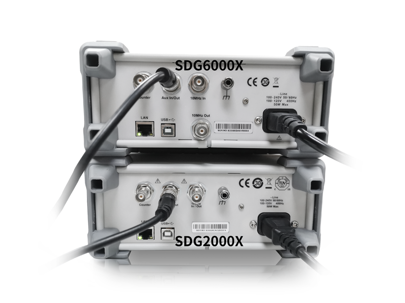
Figure 2. Connect SDG2000X and SDG6000X Aux In/Out
2) Next connect the SDG6000X 10 MHz Out port with the SDG2000X 10 MHz In/Out port, as shown in Figure 3.
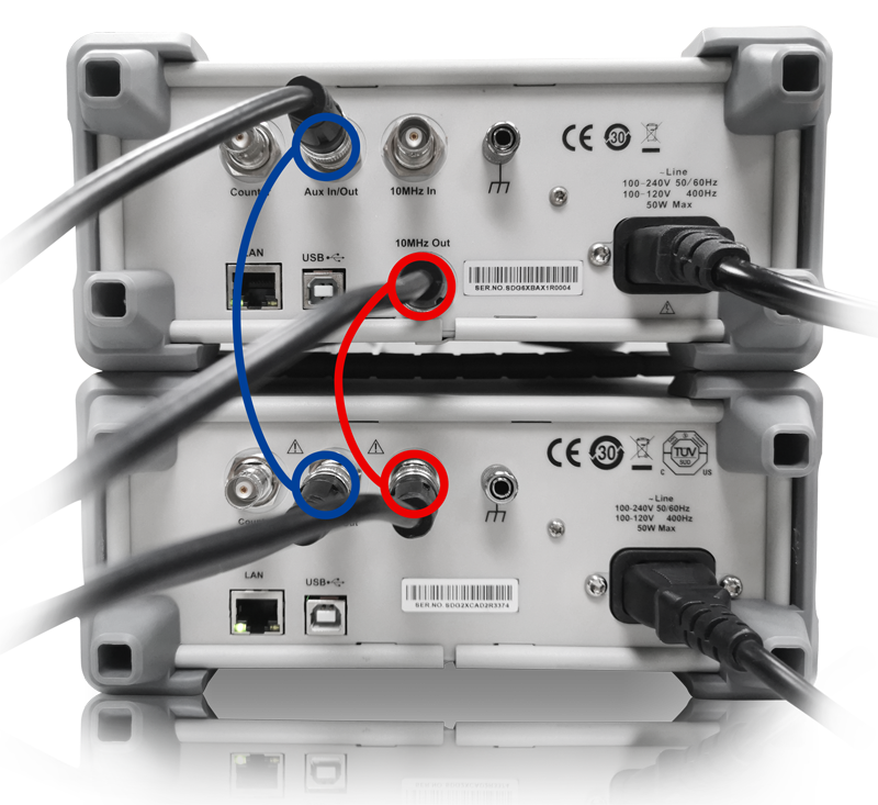
Figure 3. Connect Master 10 MHz Out to Slave 10 MHz In
2.2 Parameter settings
Set the waveform parameters, such as Frequency and Amplitude, on 4 all channels. More information on this step can found in the User Manual.
Press Utility, go to Page 2/3, choose Phase Mode, and then set both units as Phase Locked.
In this example we are setting all 4 channels as a 1 kHz, 4 Vpp square wave. CH3, CH4 signals viewed on the SDS5000X oscilloscope are output by the Slave generator, note that the phase is drifting. Open the Display/ Persist function to track it on the scope, as shown in Figure 4.
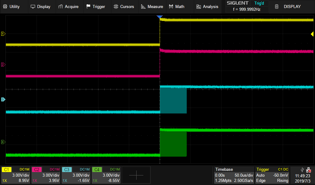
Figure 4. Four signals phase drift without synchronization
2.2.1 Set Master Device
1) Press Utility, go to Page 3/3, then press the soft key under screen to select Multi-Device Sync. The menu will enter the Multi-Device Synchronization screen, shown in Figure 5.
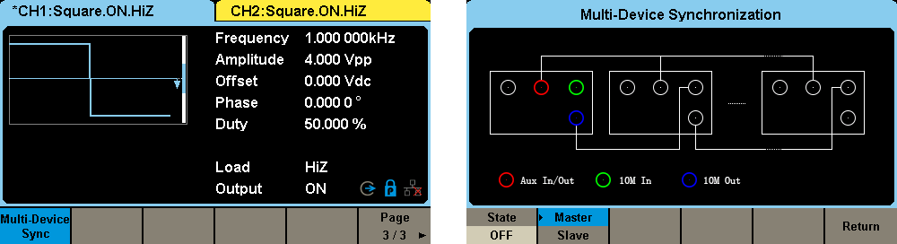
Figure 5. Multi-Device Synchronization Screen
2) Press the soft key under the screen to turn on/off this function and select it as either the Master or Slave. The Multi-Devices Synchronization menu will appear when turned on. When ”Master” appears shaded in light gray this means the device is designated as the Master device, as shown in Figure 6. When this device is set to be the master, its clock source is automatically set to internal and the 10 MHz output is enabled.
Figure 6. Turn on synchronization function
2.2.2 Set Slave Device
1) Enter into the Multi-Device Synchronization menu. Select it as Slave, Slave will be shaded in blue, as in Figure 7. As the device is set to a slave device its clock source is automatically set to external.
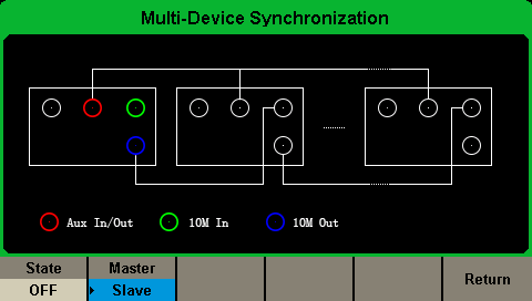
Figure 7. Select the unit as the Slave device
2) Turn on the State. Then the Slave Device Delay window will occur. Press to enter delay value, as shown in Figure 8.
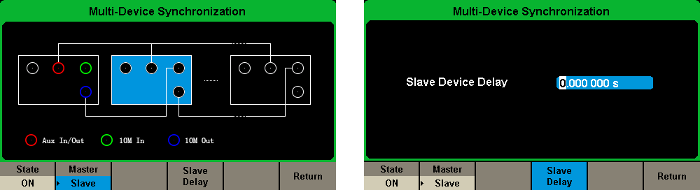
Figure 8. Set the Slave Delay
2.2.3 Synchronize the Devices
Press the soft key ”Syncs Devices” in the Multi-Device Synchronization interface of the Master device, as shown in Figure 1, to begin synchronization between the master and slave devices. Anytime a setting is changed; for example, the Slave Device Delay, ”Sync Devices” must be pressed to activate the new settings.
3. Measure on an Oscilloscope
3.1 Slave Device Delay measurement
1) Turn on Synchronization on both units, measure the Skew between CH1 and CH3. As in Figure 9.
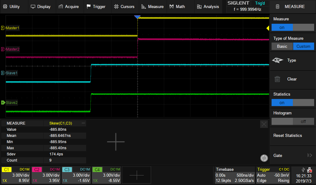
Figure 9. Measure the Skew between Master and Slave Devices
2) Enter the absolute Mean value of Skew into Slave Device Delay. This will eliminate the delay between traces that we observed with our oscilloscope. See Figure 10.
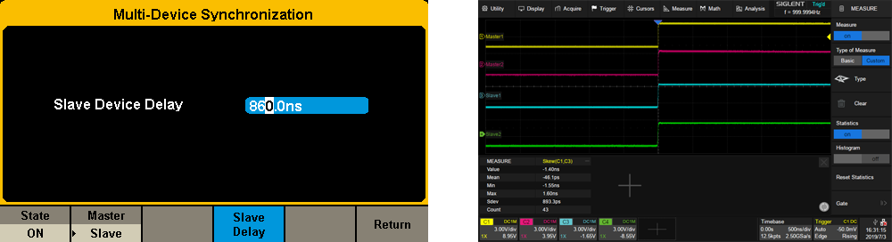
Figure 10. Eliminate the Slave Delay
3.2 Adjust phase relationship
Set CH1 Phase as 0 degrees, CH2, CH3, CH4 Phase as 180, 270, 360 degrees, respectively. The result is shown in Figure 11.
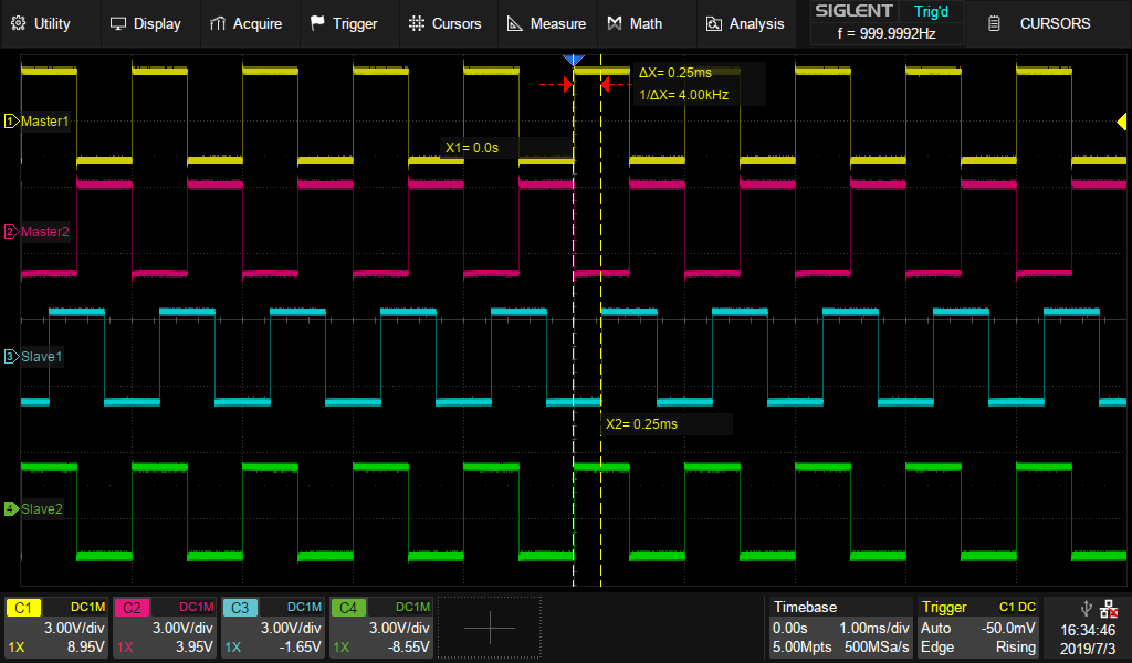 Figure 11. Adjust phase relationship