Testing Intrinsic Safety Barrier fusing and circuitry using an electronic load
December 16, 2019
From Wikipedia: Intrinsic safety (IS) is a protection technique for safe operation of electrical equipment in hazardous areas by limiting the energy, electrical and thermal, available for ignition.
The idea is to minimize the risk of fire or explosion by physically eliminating any potential source of ignition.
Many IS circuits utilize special fusing and elements that are designed to dissipate the available power below certain temperature thresholds. During a fault condition, no component within the design can exceed this temperature rating.
Testing the performance of this type of design is quite simple: Load the circuit to pull the maximum rated power and measure the temperature of all of the circuit elements (heat sinks, packaging, resistors, etc..).
In practice, you could use a power resistor network with proper heat sinking for the load but a more convenient solution is to use an electronic load like the SIGLENT SDL1000X series.
The SDL1000X is available in 200 and 300 W versions and features a Constant Power (CP) operation mode as well as Constant Resistance (CR), Constant Voltage (CV), as well as user-defined limits to ensure safe operation within the application test requirements.
- Connect the Device-Under-Test (DUT)
- Select Constant Power (CP) Mode
- Set the current (I_range) and voltage (V_range) ranges for the test
- Set the Power you wish the load to sink
- Activate the load input
After the specified time limit for your test (see your device/environment specifics for details), you can measure the components/design temperature using a thermal camera or direct temperature measurements using thermocouples and DMM like SIGLENTs SDM3000X series. In fact, the SDM3055-SC and SDM3065X-SC products feature the ability to monitor temperature on up-to-twelve thermocouples to provide multi-point temperature readings from different points on your design.
Be sure to check heatsinks and components that are expected to dissipate the most power, but also other peripheral components and traces that may carry unexpected loads during a fault.
NOTE: In this picture, we show an open power supply with no shielding or case. For more accurate measurement, we recommend leaving as much of the original design (shielding/case/metalwork) in place to get the most representative measurement possible.
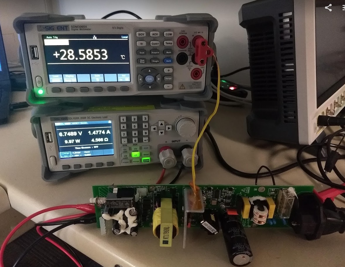
Figure 1: Example of temperature measurement of a power supply under load.