The basic output waveform and related parameters of the arbitrary waveform generator
April 23, 2020
Traditional function generators can output standard waveforms such as sine waves, square waves, and triangle waves. However, in actual test scenarios, in order to simulate the complex conditions of the product in actual use, it is often necessary to artificially create some “irregular” waveforms or add some specific distortion to a waveform. Traditional function generators can no longer meet the requirements and an arbitrary waveform generator may be a good option.
Arbitrary waveform generators can easily replace the function generators. They can source sine waves, square waves, and triangle waves like a standard function generator. In addition, they can also output pulse, noise, DC signal types, modulated signals, sweeps and bursts. Many arbitrary waveform generators currently on the market are equipped with arbitrary waveform drawing software. Through this software, theoretically, the arbitrary waveform generator can be remotely controlled to output all the signals required in the test process.
So, what types of waveforms can an arbitrary waveform generator output?
What parameters are available for an arbitrary waveform?
How to measure the quality of the output waveform?
- Sine Wave / Cosine Wave
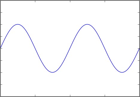
Figure 1 Sine wave / Cosine wave
Sinusoidal (sine) and cosine waves are the two most familiar waveforms in electronics.
Sine/cosine waves are defined as follows.
![]() (Formula 1)
(Formula 1)
OR
![]() (Formula 2)
(Formula 2)
Where A represents the amplitude of the sine wave, represents the angular frequency, and represents the initial phase, which can be omitted in the general calculation. The sine and the cosine waves are essentially the same, but the initial phase differs by 90 °.
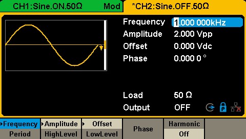
Figure 2 Sine wave setting interface in SDG1000X
These three parameters are as shown in Figure 2. The frequency and period related to the angular frequency can be set in the arbitrary waveform generator, and the conversion relationship between them is:
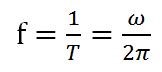 (Formula 3)
The frequency of a generator, like the SIGLENT SDG2122X function / arbitrary waveform generator sine wave can be set up to 120 MHz. Usually, the nominal maximum output frequency of the arbitrary waveform generator often refers to the maximum frequency of its sine wave output.
You can also set the amplitude, A. When the output impedance is set to the “high impedance” state, the maximum output amplitude of the SDG2122X can reach 20 Vpp.
The initial phase can be set by clicking the corresponding button in the [Phase] menu. The range of the initial phase can be set between -360 ° and + 360 °.
From the time domain perspective, the parameters and waveforms of the sine and cosine waves are relatively simple. However, all electronic devices have more or less distortion, and arbitrary waveform generators are no exception. Let’s observe sine and cosine waves in the frequency domain.
The Fourier transform corresponding to the time domain function represented by Formula 1 is:
![]() (Formula 4)
(Formula 4)
The spectrum diagram represented by Formula 4 is shown in the figure below:

Figure 3: Cosine spectrum/frequency domain
Looking at the cosine spectrogram (showing amplitude vs. frequency) in Figure 3, we can find that the frequency of a sine/cosine wave can be represented by a single line on the spectrum. Signals that occupy only one frequency are called “monotone” because they only have one frequency component.
In engineering, due to the non-ideal characteristics such as the non-linearity of the circuit, the generated sine wave is often not an ideal monotone signal, but may contain other frequencies. Collective “unwanted” frequencies are often lumped together under the term distortion. Some common contributors to distortion are harmonics and spurs.
- Harmonic distortion
The fundamental frequency of a signal is the lowest frequency component of a periodic signal. Harmonics are the frequency components of the signal that are integer multiples of the fundamental. Distortion is the ratio of signal power to maximum harmonic power, usually in dB, as shown in the following figure:

Figure 4: Harmonic distortion
Another index to measure the performance of harmonic distortion is total harmonic distortion (THD), which refers to the ratio of the root mean square of the amplitude of each harmonic (usually taken to the 6th harmonic in engineering) to the signal amplitude, as shown in Formula 5, usually expressed in %. When an SDG2000X outputs 0 dBm, 10 Hz ~ 20 kHz sine wave, the total harmonic distortion is 0.075% at most.
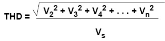 (Formula 5)
- Non-harmonic spurs
In addition to harmonics, the distortion caused by nonlinearity may also be some other spectral components, such as the intermodulation products of the signal (or its harmonics) and the clock signal. It is necessary to define other index-non-harmonic spurs to measure.
The size of the spur is usually expressed by the spurious-free dynamic range (SFDR) (see Figure 5), which refers to the ratio of the signal power to the maximum spurious power. The unit is usually dB. Please note that the definition of spurs in some places includes harmonic and non-harmonic spurs, but in arbitrary waveform generators, spurs only refer to distortions other than harmonics.
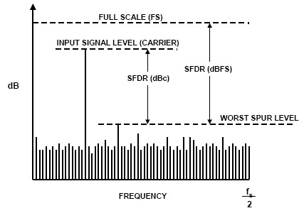
Figure 5: SFDR
For More information, please click here.