Product Overview
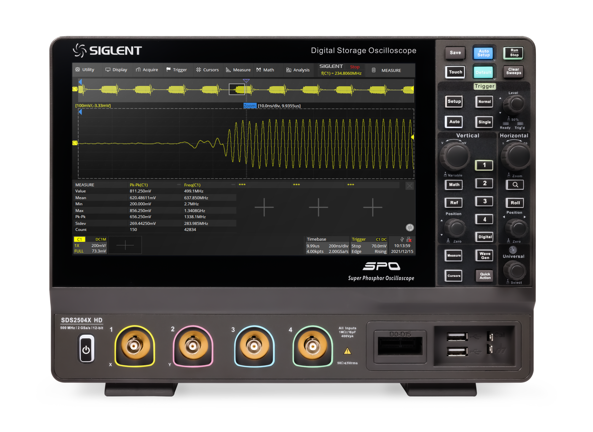
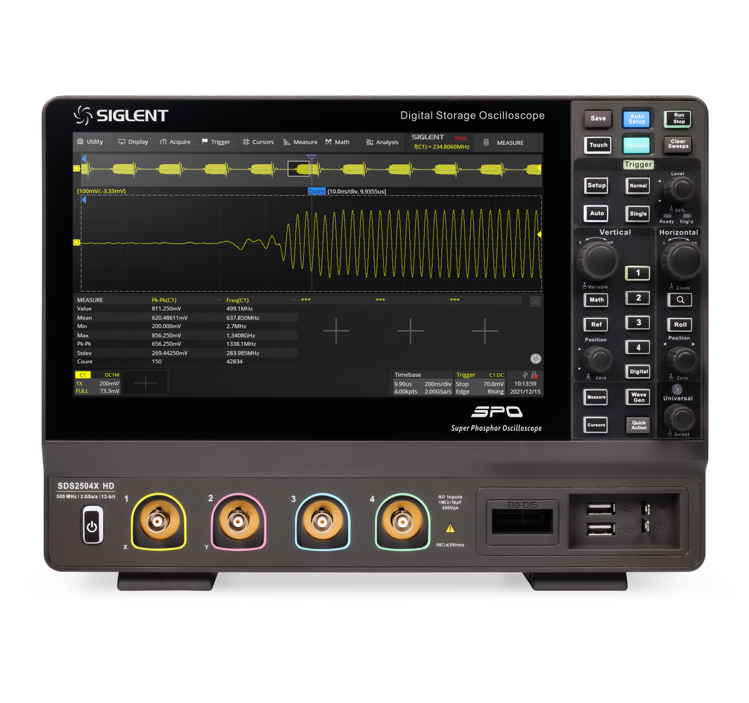
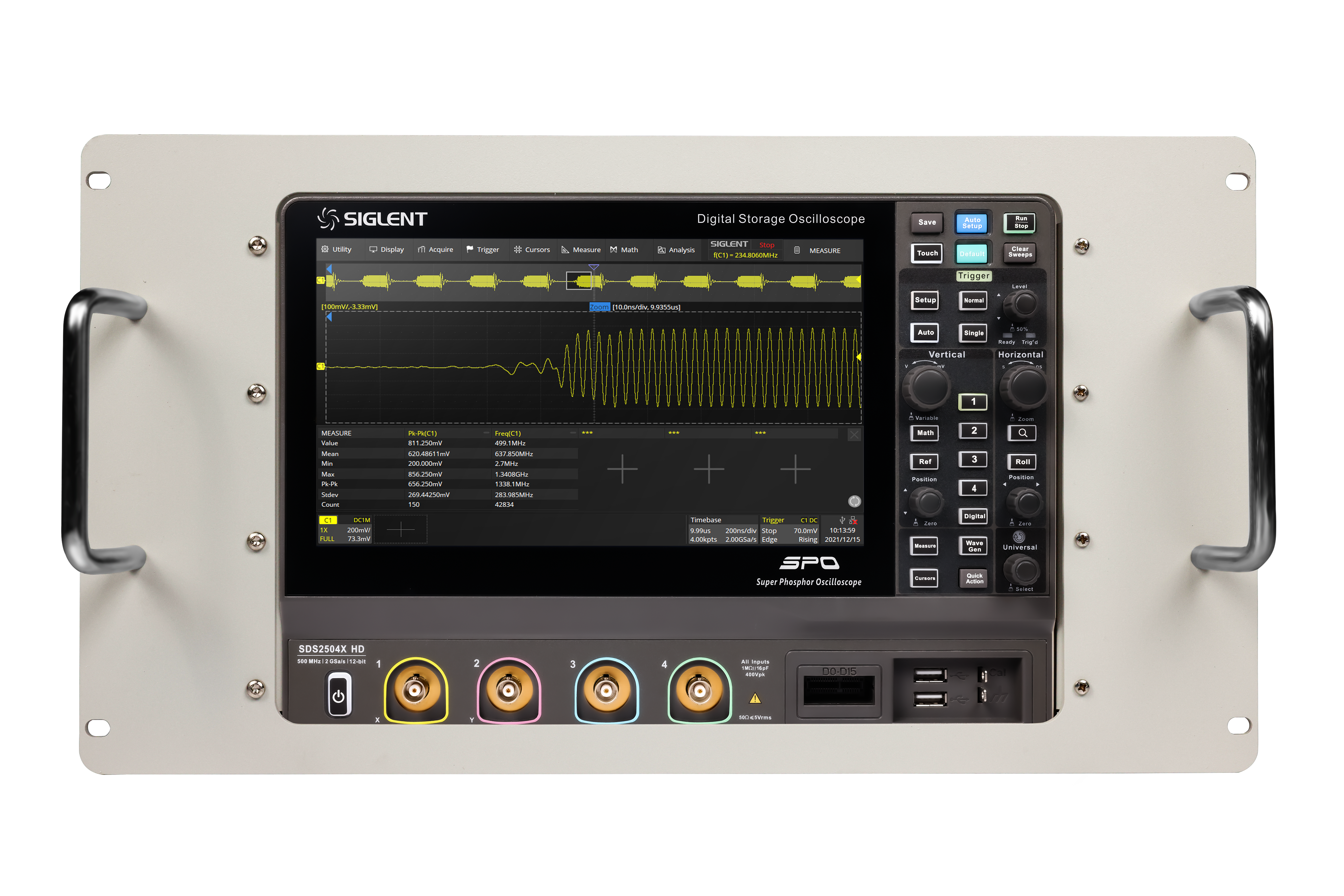
SIGLENT’s SDS2000X high-resolution digital oscilloscopes are based on 2 GSa/s, 12-bit Analog to Digital converters and front ends with excellent noise floor performance. SDS2000X HD oscilloscopes are available in bandwidths of 350 MHz and 200 MHz, have a maximum record length of 200 Mpts/ch, and display 4 analog channels + 16 digital channels mixed-signal analysis ability.
The SDS2000X HD series employs Siglent’s SPO technology with a maximum waveform capture rate of up to 100,000 wfm/s (normal mode, up to 500,000 wfm/s in Sequence mode), 256-level intensity grading display function plus a color temperature display mode. It also employs an innovative digital trigger system with high sensitivity and low jitter. The trigger system supports multiple powerful triggering modes including serial bus triggering. Tools such as History waveform recording, Search and Navigate functions, Mask Test, Bode Plot, Power Analysis and Histogram allow for extended waveform records to be captured, stored, and analyzed. An impressive array of measurement and math capabilities, options for a 25 MHz arbitrary waveform generator, as well as serial decoding are also features of the SDS2000X HD digital oscilloscope.
The large 10.1’’ display capacitive touch screen supports multitouch gestures, with the addition of a user-friendly UI design, which can greatly improve the operation efficiency. It also supports mouse control and remote web control over LAN.
Key Features
- 12-bit High Resolution
- 12-bit Analog-Digital Convertors with sample rate up to 2 GSa/s
- Front ends with 70 μVrms noise floor @ 500 MHz bandwidth and 0.5% DC gain accuracy
- 4 analog channels, up to 350 MHz bandwidth (upgradable to 500 MHz)
- SPO technology
- Waveform capture rate up to 100,000 wfm/s (normal mode), and 500,000 wfm/s (sequence mode)
- Supports 256-level intensity grading and color temperature display modes
- Up to 200 Mpts/ch record length
- Digital trigger system
- Intelligent trigger: Edge, Slope, Pulse, Window, Runt, Interval, Dropout, Pattern, Qualified, Nth edge, Setup/hold, Delay and Video (HDTV supported). Zone Trigger simplifies advanced triggering
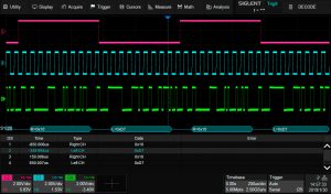
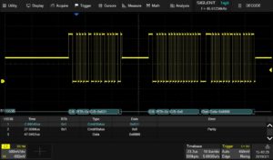
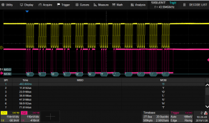
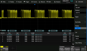
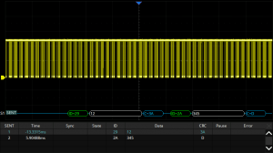
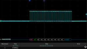
- Serial bus triggering and decoder, supports protocols I2C, SPI, UART, CAN, LIN, CAN FD, FlexRay, I2S, MIL-STD-1553B, SENT and Manchester
- Segmented acquisition (Sequence) mode, dividing the maximum record length into multiple segments (up to 80,000), according to trigger conditions set by the user, with a very small dead time between segments to capture the qualifying event
- History waveform record (History) function, the maximum recorded waveform length is 80,000 frames
- Automatic measurements on 50+ parameters, supports statistics with histogram, track, trend, Gating measurement, and measurements on Math, History and Ref
- 2 Math traces (2 Mpts FFT, addition, subtraction, multiplication, division, integration, differential, square root, etc.), supports formula editor
- Abundant data analysis functions such as Search, Navigate, Digital Voltmeter, Counter, Waveform Histogram, Bode plot and Power Analysis
- High Speed hardware-based Average, ERES; High Speed hardware-based Mask Test function, with Mask Editor tool for creating user-defined masks
- 16 digital channels
- Built-in 25 MHz waveform generator (option SDS2000HD-FG)
- Large 10.1” TFT-LCD display with 1024 * 600 resolution; Capacitive touch screen supports multi-touch gestures
- Interfaces include: USB Hosts, USB Device (USBTMC), LAN (VXI-11/Telnet/Socket), Pass/Fail, Trigger Out
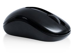
- Built-in web server supports remote control over the LAN port using a web browser. Supports SCPI remote control commands. Supports external mouse and keyboard
The new 12-bit resolution SIGLENT HD oscilloscope has been an awesome addition to my lab bench. With greater dynamic range, lower noise floor, and larger offset adjustability of the SIGLENT HD compared to my old Tek DPO scope, I can isolate and view high-frequency signals on my PCB with much greater clarity.
With the SIGLENT HD I have been able to:
- Isolate and mitigate high-frequency ringing and noise more quickly and easily.
- Tune snubber circuits more quickly and accurately.
- Run more accurate transient response tests.
- Easily measure switch node jitter and unexpected circuit glitches with the deep memory.
- Use the internal function generator and Bode Analysis Mode to measure power supply control loops in circuit.
Highly recommended!!
– Andrew, FAE at a leading semiconductor company June, 2022
Product Characteristics
12-bit High Resolution View more
12-bit High Resolution
SDS2000X 12-bit resolution shows you more details and less noise on the waveform.
Low noise floor: Only 70 µVrms at 500 MHz bandwidth.
0.5% DC gain accuracy.
High Waveform Update Rate View more
High Waveform Update Rate
With a waveform update rate of up to 100,000 wfm/s, this digital oscilloscope can easily capture unusual or low-probability events. In Sequence mode, the waveform capture rate can reach 500,000 wfm/s.
Deep Record Length View more
Deep Record Length
Using hardware-based Zoom technique and record length of up to 200 Mpts, users can select a slower timebase without compromising the sample rate, and then quickly zoom in to focus on the area of interest.
Multiple Trigger Functions View more
Multiple Trigger Functions
SDS2000X trigger functions include: Edge, Slope, Pulse, Video, Windows, Runt, Interval, Dropout, Pattern, Qualified, Nth edge, Setup/hold, Delay, and serial trigger.
Trigger Zone View more
Trigger Zone
Trigger Zone is available for advanced triggering.
Advanced Math Function View more
Advanced Math Function
In addition to the traditional (+, -, X, /) operations, FFT, integration, differential, square root, and more are supported. Formula Editor is available for more complex operations. 2 math traces are available.
Hardware-accelerated FFT supports up to 2 Mpts operation. This provides high-frequency resolution with a fast refresh rate. The FFT function also supports a variety of window functions so that it can adapt to different spectrum measurement needs. Three modes (Normal, Average, and Max hold) can satisfy different requirements for observing the power spectrum. Auto peak detection and markers are supported.
Measurements of a Variety of Parameters View more
Measurements of a Variety of Parameters
Parameter measurements include 4 categories: horizontal, vertical, miscellaneous, and CH delay providing a total of 50+ different types of measurements. Measurements can be performed within a specified gate period. Measurements on Math, Reference, and History frames are supported.
Parameter Statistics Function View more
Parameter Statistics Function
Statistics show the current value, maximum value, minimum value, standard deviation, and mean value of up to 12 parameters simultaneously. A histogram is available to show the probability distribution of a parameter. Trend and Track are available to show the parameter value vs. time.
For horizontal parameters such as period, all results are extracted from a frame, instead of just calculating the first one. This accelerates statistics on horizontal measurements much more and enables distribution observation in a frame using Histogram and Track.
History Mode View more
History Mode
SDS2000X HD’s history function can record up to 80,000 frames of waveforms. The recording is executed automatically so that the customer can playback the history waveforms at any time to observe unusual events and quickly locate the area of interest using the cursors or measurements. The failed frames of the Mask Test can be stored as history.
Sequence Mode View more
Sequence Mode
Segmented memory collection will store the waveform into multiple memory segments (up to 80,000) and each segment will store a triggered waveform as well the dead time information. The interval between segments can be as small as 2 μs. All of the segments can be played back using the History function.
Search and Navigate View more
Search and Navigate
The digital oscilloscope can search events specified by the user in a frame. Events flagged by the Search can be recalled automatically using Navigate. It can also navigate by time (delay position) and history frames.
Serial Bus Decode View more
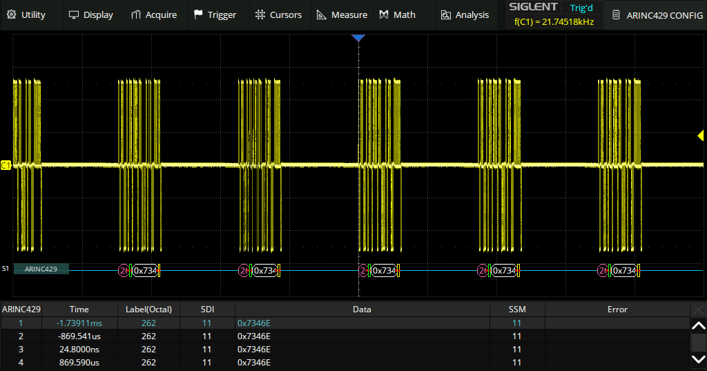
Serial Bus Decode
Display the decoded characters through the events list. Bus protocol information can be quickly and intuitively displayed in tabular form. I2C, SPI, UART, CAN, LIN, CAN FD, FlexRay, I2S, MIL-STD-1553B, SENT, and Manchester are supported.
Hardware-based High-Speed Mask Test Function View more
Hardware-based High-Speed Mask Test Function
SDS2000X HD oscilloscopes utilizes a hardware-based Mask Test function, performing up to 14,000 Pass / Fail decisions each second. It is easy to generate user-defined test templates to provide trace mask comparisons, making it suitable for long-term signal monitoring or automated production line testing.
Bode Plot View more
Bode Plot
The digital oscilloscope can control the built-in waveform generator or a stand-alone SIGLENT generator, to scan the amplitude and phase-frequency response of the DUT, and display the data as a Bode Plot. This makes it possible to replace expensive network analyzers in some applications.
Power Analysis (Optional) View more
Power Analysis (Optional)
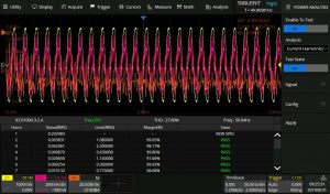
SDS2000X HD’s Power Analysis option provides a full suite of power measurements and analysis, which greatly improve the measurement efficiency in switching power supplies and power devices design.
Digital Channels / MSO (Optional) View more
Digital Channels / MSO (Optional)
Four analog channels plus 16 digital channels enable users to acquire and trigger the waveforms then analyze the pattern, simultaneously with one instrument.
Built-in 25 MHz Waveform Generator (Optional) View more
Built-in 25 MHz Waveform Generator (Optional)
The built-in waveform generator can output waveforms with up to 25 MHz frequency and ±3 V amplitude. Six basic waveforms together with multiple types of predefined waveforms and as user-defined arbitrary waveforms are supported.
Complete Connectivity View more
Complete Connectivity
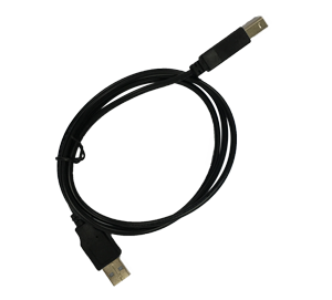
USB Host 2.0 x3, USB Device 2.0 (USBTMC) , LAN (VXI-11/Telnet/Socket), Auxiliary output (Pass/Fail, Trigger Out), etc.
Standard Accessories
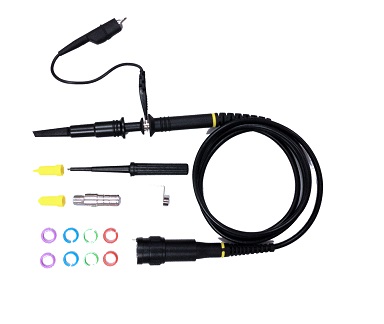
Passive Probes
