Electromagnetic Compliance: Pre-Compliance Test Basics
October 19, 2017
Today’s products are subjected to more standardized test requirements than ever before. These standards (UL, CE, and others) ensure consumer safety and add to the quality and dependability of products. But, these tests also add cost to the manufacturer, which is passed to the consumer. This is especially true with electronics.
Any product that has the ability to generate radio frequency (RF) signals and is slated for commercial use is subject to meeting certain limits on the amplitude of radio frequency (RF) signals that it can produce. Unintended RF is typically referred to as electromagnetic interference (EMI) and measuring the performance of a product with respect to these limits is known as electromagnetic compliance (EMC) testing.
These tests are mandated and enforced by government agencies (the Federal Communications Commission in the USA) that oversee the geography into which a product will be sold. They are also responsible for defining the test configuration (physical location, layout, distances, test equipment, and settings) as well as specifying the minimum performance of the product type.
The primary goal for setting these limits is to ensure that products don’t interfere with the normal operation of existing products and broadcast channels (radio and TV, for example). Products that don’t meet these standards are not available for legal sale within the country and companies may have to halt sales, recall products, and/or pay fines if products are found to be non-compliant.
EMC testing can be self-certified. That is, a manufacturer can perform the testing and certify that they pass the limits set forth for their product. In practice, most companies send their products to a third-party test lab to perform the required testing. This is due, in part, to the special equipment and knowledge required to successfully perform EMC testing.
An accredited third-party lab has the expertise and equipment to quickly and accurately determine the performance of a product vs. the government limits on that product type. Full compliance testing in a lab is ideal and highly recommended when you are confident that the product meets or exceeds the limits, but testing in a lab can be expensive. Standard rates currently hover between $1000 and $2000 per day and there can be additional difficulties scheduling time to get into the lab. Additional issues arise if the product fails. Every failed compliance test requires a fix and retest. If the first fix doesn’t work, another fix is applied, and the product is retested. This process continues until the product passes the testing requirements.
Fortunately, there are test methods and techniques that can help minimize the amount of lab time that may be required to pass compliance testing. These pre-compliance test techniques can be implemented early in the design process and applied throughout the development cycle. Testing EMI during product development instead of after will lessen the overall cost and shorten the total development time. It will also deepen your understanding of the RF footprint of your product and allow you to make adjustments before the design is finalized, saving you time and money. The knowledge gained during these troubleshooting stages can be also applied to future designs.
RADIATED EMISSIONS/NEAR FIELD
Radiated emissions compliance testing involves measuring the RF power that emanates from a product over a specified frequency range using an antenna and a spectrum analyzer and comparing it to the standard limits for that product class.
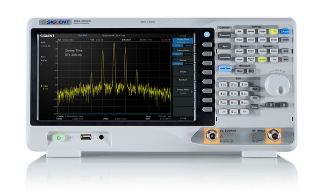 Figure 1: A Siglent SSX3021X 2.1GHz spectrum analyzer.
Accurately measuring the radiation emitted from a product requires the reduction of external RF sources like radio stations and Wi-Fi. Throughout most of the 20th century, outdoor testing sites located far from RF sources could be utilized. Over the past 20 years, the exponential increase in RF sources (Wi-Fi, Bluetooth, cell phones, and the like) have made these open-air test sites (OATS) facilities practically extinct. Most compliance labs utilize special rooms (anechoic and semi-anechoic chambers) that minimize the amount of external RF. The device-under-test (DUT) is placed on a rotating stage atop a non-conductive table and the antenna orientation (height and rotation) can also be adjusted. This allows a complete survey of the emitted radiation from the DUT in three dimensions. A basic diagram of a common radiated emissions test is shown in Figure 2.
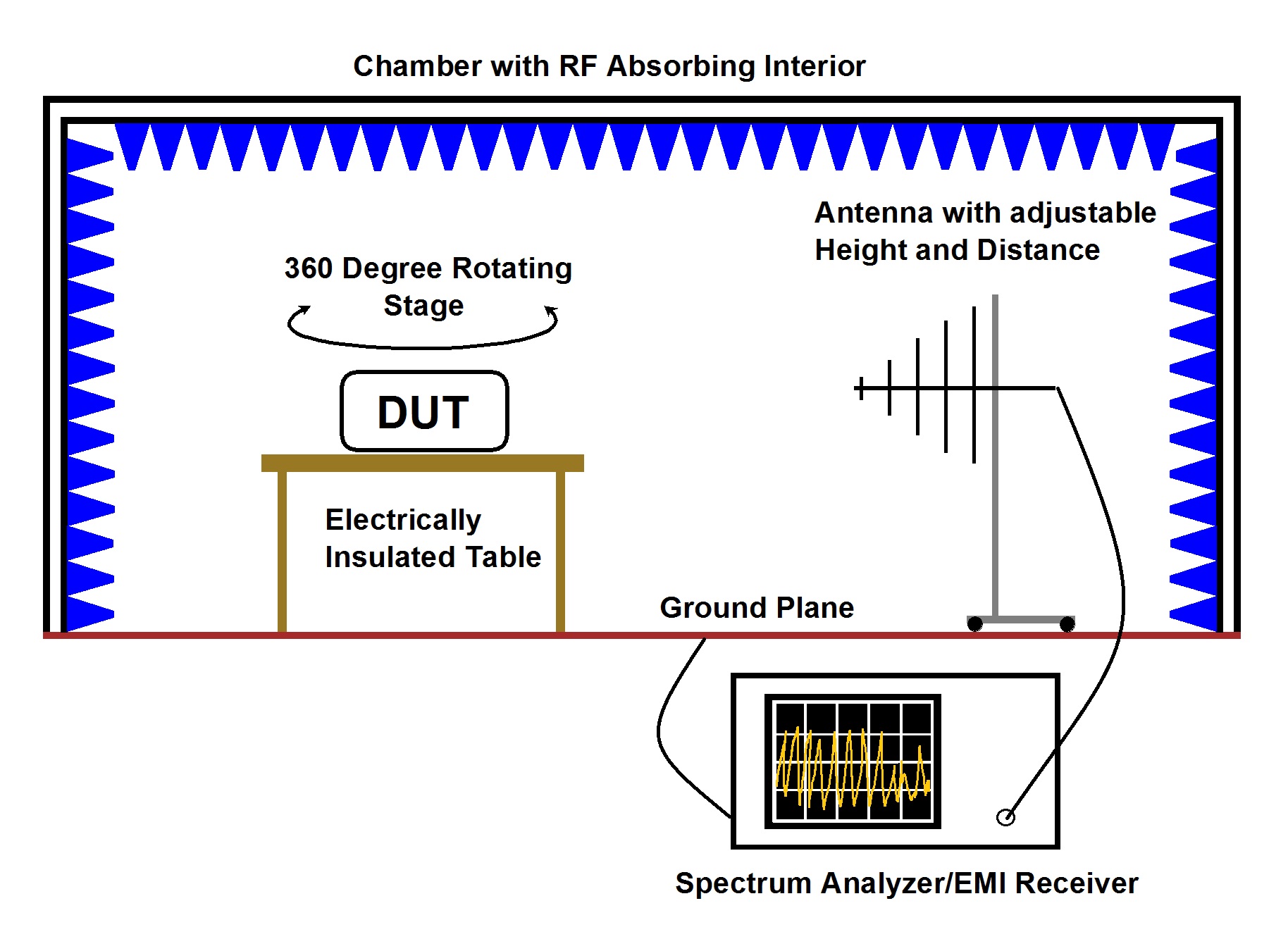 Figure 2: A common radiated emissions compliance test configuration.
Correlating the potential compliance performance of a DUT from data captured during radiated pre-compliance tests can be a tricky process. The environmental RF, reflections, and absorption can make repeatable measurements difficult at best and most organizations don’t have the budget to build and maintain a special chamber designed for the task. Shielded tents and fixtures can be used to minimize environmental RF and periodically measuring the environmental RF can help provide a clearer picture of the radiated emissions from your product, but near-field measurements are the primary method used to identify the potential problem areas of a design because the measurements are less prone to environmental effects and they are more convenient due to the smaller size of the probes.
The near-field probing technique involves using a loop or point probe connected to a spectrum analyzer. The two most common types of near-field probes available are magnetic (H) and electric (E) field probes. They are effective because they are fairly immune to environmental RF. During a test, the probe is placed close to the DUT and is slowly used to scan across different areas. The distance from the DUT varies, but less-than-a-half-inch is a good starting point. Scans can be performed at every step of the design process, including discrete circuit elements, traces, sub-assemblies, all the way up to finished products and enclosures. The most likely problem areas include cut-outs, seams, and gaps in metal enclosures, LCD/display ribbon cables, USB/LAN ports, and switching power supply circuits. While scanning, observe the analyzer and look for increased amplitudes on the display. Note the frequency bands with the most prevalent signals. These could be problematic EMI sources. Figure 3 shows commercial near-field probes and figure 4 shows an example of using a near-field probe and spectrum analyzer to determine problem areas of a design.
 Figure 3: Siglent SRF5030 Near-Field Probe kit includes 2 loop and 2 point magnetic (H) field probes, cable, and adapter. Only the probes are shown.
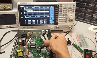 Figure 4: Scanning a board using a Siglent SSA 3021X Spectrum Analyzer and an SRF5030 near-field probe.
CONDUCTED EMISSIONS
Products that receive power by wires or cords to the national power distribution grid need additional testing. In most cases, this means any product that is connected to a wall outlet but can include industrial connections as well. This is known as conducted emissions testing which involves measuring the RF energy that originates in the product and propagates down the power cord onto the power grid. This is important because excessive RF on the power lines can cause interference with AM radio and other broadcast bands.
Conducted emissions testing requires a spectrum analyzer, two bonded metal plates that function as ground planes, and a Line-Impedance-Stabilization-Network (LISN). The LISN supplies power to the device-under-test (DUT) and diverts the RF from the DUT to the spectrum analyzer, where it can be measured. Additional transient protection and attenuation can be added to help minimize the risk of damage to the sensitive RF input of the analyzer. A typical conducted emissions setup is shown in figure 5.
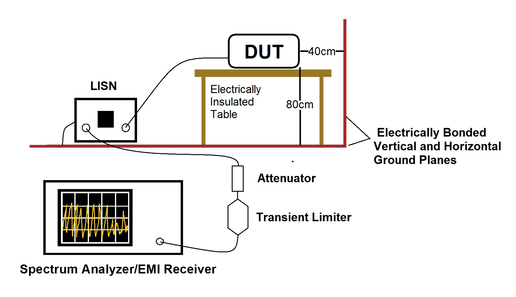 Figure 5: Typical conducted emissions compliance configuration. A transient limiter and attenuator are recommended to protect the input of the analyzer.
The cost for emulating a fully compliant conducted emissions test setup is relatively low. This makes correlating pre-compliance data to expected compliance performance significantly easier than with radiated emissions.
IMMUNITY/SUSCEPTIBILITY
In the US, compliance testing for consumer products focuses on maintaining the conducted and radiated emissions of a product. But, there is another aspect of compliance testing that we would like to cover. Many consumer products being sold in US、Europe and Asia, will likely require immunity testing. These tests are designed to ensure that a product can operate correctly when it is in an environment that contains specific RF signals. Immunity tests can also be referred to as susceptibility testing, as the tests are determining if a product is “immune to” or “susceptible to” interference.
The basic configuration for immunity testing is shown in figure 6 below. An RF source is used to deliver specific RF power over defined frequency bands and the operation of the EUT is observed. The EUT should maintain normal operating functions throughout the test.
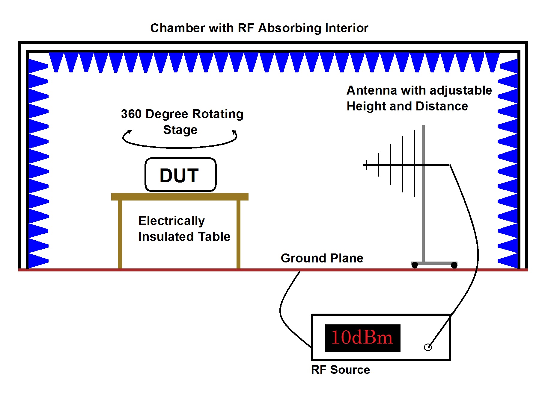 Figure 6: A typical immunity test. Note that an RF absorbing chamber is used to contain the RF power and minimize the leakage into the environment.
Note that the configuration of the test is very similar to a radiated emissions test, but instead of measuring the amount of radiated RF power from the EUT with a spectrum analyzer, the EUT is actually being radiated by RF power being delivered by an antenna and RF source. The RF absorbing chamber is also being used. This is to prevent the RF from escaping into the environment and causing issues with the world “outside” of the test lab. It is critical to stay below the published standards for unlicensed intentional radiators if you perform this test. At a minimum, you could cause disturbances with Wi-Fi or other networks nearby. Worst case, you could cause issues with other systems that are critical to ensure the safety of people. Please be cautious and follow the regulations for your region.
CONCLUSION
Products with the ability to create RF energy need to be tested to ensure that they comply with government regulations. The two most common compliance tests radiated and conducted emissions tests. While companies may choose to self-certify, it is recommended to have a third-party lab perform compliance tests. But, third-party labs can be expensive and scheduling time in the lab can be difficult.
Implementing in-house pre-compliance testing of near-field and conducted emissions test techniques at each stage in the design process can minimize the total development time for your products, lower the cost of design, and decrease the amount of testing on future products.
REFERENCES
Basic Guidelines: Federal Communications Commission (www.fcc.gov)
Unintentional Radiators: Title 47, Part 15, Subpart B of the Electronic Code of Regulations for the USA
For more information, check the SSA3000X webpage, or contact your local Siglent office.