How do I determine what bandwidth of scope I require for my application?
October 24, 2017
The bandwidth of a digital oscilloscope, often called analog bandwidth, refers to the bandwidth of the front-input amplifier of the oscilloscope and is equivalent to a low pass filter. Oscilloscope bandwidth is defined as the frequency at which the amplitude of the observed signal drops by -3 dB (or drops to 70.7% of its actual value) as we increase the test signal’s frequency as plotted on the amplitude-frequency characteristic curve (Figure 1).
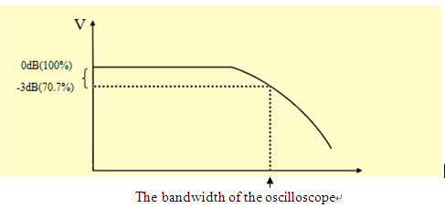
Figure 1: The amplitude-frequency characteristic curve.
If the input signal is a sine wave, the bandwidth of the oscilloscope must be equal to or greater than the fundamental frequency of the input signal. For non-sinusoidal waveforms (square waves, pulses, digital communications, etc..), a bandwidth 5 or more times the fundamental frequency is an adequate starting point but may be too low for precise rise time measurements. A bandwidth of 10 times the fundamental frequency (1st order harmonic) may be more appropriate.
The frequency content (or bandwidth) of the waveform affects the measurement in two ways:
1. The higher order harmonics are filtered due to the low bandwidth, and the original waveform shape distorts, becoming similar to a sine wave.
2. The displayed and measured rise time will be distorted and the amplitude will error will increase.
Figure 2 is a 10 MHZ square wave, which is displayed on a 200 MHz bandwidth and a 10 MHz bandwidth oscilloscope.
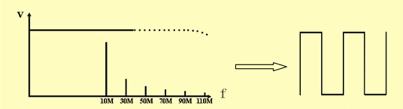
200 MHz Bandwidth oscilloscope – Correct
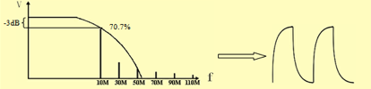
10 MHz Bandwidth oscilloscope – Distortion
Figure 2: A 10 MHz square wave viewed on a 200 MHz bandwidth oscilloscope vs a 10 MHz oscilloscopes. Note how the 10 MHz scope attenuates higher frequency components which distort the waveform as viewed on the instrument.
Rise time is typically defined as the length of time it takes for the signal to go from 10% to 90% of its maximum value.
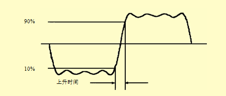
Figure 3: Rise Time
The rise time measurement capability of an oscilloscope is directly related to its bandwidth.
The relationship is as follows:
T (rise) = 0.35 / oscilloscope bandwidth (below 1 GHz)
The measurement error can be easily calculated. Let’s take a look at a 100 MHz bandwidth, 3.5 ns rise time square wave as it would be measured by a 100 MHz bandwidth oscilloscope:
The rise time of the 100 MHz oscilloscope = 0.35/100 MHz = 3.5 ns
The rise time of input signal = ![]()
Measurement error = (4.95 ns – 3.5 ns) / 3.5 ns = 0.414 = 41%
To improve the accuracy of measurement, let’s perform the same calculations, but this time, let’s select an oscilloscope with a bandwidth that is 5 times higher:
The rise time of 500 MHZ oscilloscope = 0.35/500 MHz = 0.7 ns
The displayed signal rise time = ![]()
Measuring error = (3.569 ns – 3.5 ns) / 3.5 ns = 0.0198 = 2%
This is sometimes referred to as the five times rule of the oscilloscope bandwidth selection:
The required bandwidth of an oscilloscope = the highest frequency component of the measured signal x 5
The measurement error of an oscilloscope using the five times rules will be less than ± 2%, which is enough for most measurements.