Generating Multi-Phase Waveforms
October 23, 2017
Applications for multi-phase waveforms are everywhere – in Power-related applications, I/Q modulation, Automobile applications, Components, etc.
While Siglent’s SDG2000X, and SDG5000, (& SDG1000) arbitrary waveform function generators all have two independent outputs with adjustable phase offsets, some applications call for three or more different signals, each with a phase relationship that is locked-to but adjustable from the other waveform phases. There are two main methods to accomplish this. For this application note we will use the SDG5000 generator.
Method 1
Each SDG5000-series generator has a built-in 10 MHz time base output port on the rear panel as well as an external 10 MHz time base input port. Because each SDG5000 has two independent front-panel waveform outputs along with the ability to separate them by a calibrated amount of phase, we can use one SDG5000 for every two phases that is needed.
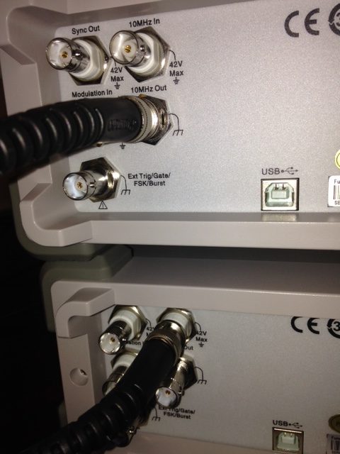
If only 3 or 4 phases are required for the application, simply connect the 10 MHz output from the first SDG5000 (Unit 1) to the 10 MHz input port of the second SDG5000 (Unit 2) via a suitable coaxial cable connection as shown in Photo 1. In this photo, the top generator’s time base is connected (Unit 1) to the bottom generator’s 10 MHz reference input (Unit 2) via a coaxial cable.
It should be noted that if more than 3 or 4 phases are required (more than 2 generators) the time bases should not be connected in parallel (as with using T-connectors). In this case, Unit 1’s 10 MHz output port is connected to Unit 2’s 10 MHz input port. Next, Unit 2’s 10 MHz output port is connected to Unit 3’s 10 MHz input port, etc.

The next step is to set Unit 2 so that it uses the external 10 MHz time base (from Unit 1).
On the Unit 2 keyboard:
a) Press UTILITY key on the front panel.
b) Press key located directly under “System” on the screen’s menu.
c) Choose More selection
d) Chose CLKSource and push key to select External
e) Press Done
![]()
The two SDG5000 generators are now sharing the Unit 1 time base. Notice that the two outputs from Unit 1 are synchronized1 and have adjustable phases. The same is true for the two outputs from Unit 2. However, there will be a phase offset of some arbitrary value existing between Unit 1’s two outputs and Unit 2’s two outputs. This is due to the fact that the two generators are locked to the same time base but the outputs were not synchronized upon power-up2.
The two outputs on Unit 2 can now be adjusted to be in phase (using and oscilloscope or other suitable phase displaying device) to the outputs from Unit 1. Once Unit 2’ outputs are in phase with Unit 1’s outputs then make note of the phase readings for the output’s from Unit 2. These ‘offset’ values will then need to be subtracted from any subsequent phase adjustment readings.
Method 2
In Method 2, Unit 2 will use its own internal time base so CLKSource will be set to Internal on Unit 1 and Unit 2. In this method, Unit 1 will trigger Unit 2 (and additional units if they are used) so that a residual phase offset is not present and does not need to be subtracted out of the settings.
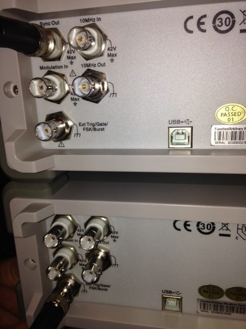
On the rear panel, connect the Sync Output from Unit 1 with a coaxial cable to the Ext Trig/Gate/FSK/Burst input connector on the back panel of Unit 2 (Photo 2).

Once the connections in both Photo 1 and Photo 2 are made the generators are ready to set up from the front panel.
Unit 1:
a) Choose: UTILITY > System> More>CLK Source. Use the Internal Clock source for Unit 1. Select Done.
b) UTILITY > Sync > State (Choose ON). Select CH 1 then Done.
c) Push the BURST button. Turn the Burst function to On. Make sure the unit is in NCYCLE mode and set for 1 cycle.
d) Repeat steps b and c for CH 2.
Unit 2:
a) Choose: UTILITY > System> More>CLK Source. Use the INTERNAL Clock source for Unit 2. Select Done.
b) Push the BURST button. Turn the Burst function to On. Make sure the unit is in NCYCLE mode and set for 1 cycle.
c) Selector More then set the Edge selection for Up. Source should be set for External.
d) Repeat step b for CH 2.
To Synchronize the Two Generators
On Unit 1:
a) UTILITY>Sync>State Off>Done
b) Return to UTILITY>Sync>State On>Done
The Phase adjustment for the two Unit 2 outputs can be adjusted from the Starting Phase screen under Burst for each of the two channels.
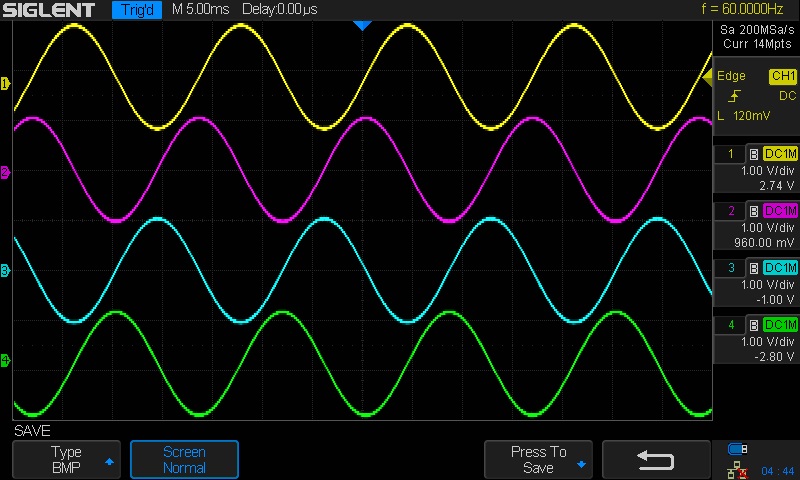
This photo (Photo 3) shows 4 output sinewaves generated from two separate SDG5000 generator. Channel 2 is set to a 90 deg phase, Channel 3 (Unit 2, Channel 1) is set to 180 degrees and Channel 4 (Unit 2, Channel 2) is set to 270 degrees. Notice that the phase shifts are Leading.

If CH1 and CH2 are out of phase for either unit during set up choose EqPhase from the menu in order to align the two phases.

