Create variable duration waveform bursts using Gated Bursting techniques with SIGLENT SDG generators
August 23, 2018
Some applications require sourcing a waveform with variable duration on and off times and/or delivering variable width bursts of a specific waveform type.
This is typically the case when you want to control the amount of energy delivered to the device-under-test (DUT). Bursts of signals with dwell or dead time between bursts can limit the amount of energy delivered to a DUT.. which can decrease heating of the DUT.
Creating an arbitrary waveform with the repeating pattern may be one option, but this technique may add effort and expense. Long dwell times use up limited arbitrary waveform samples. In this tip, we are going to introduce gated bursting and show you how to build a simple setup to source variable duration output bursts.
NOTE: When creating any waveform, it is best to start with a detailed diagram of the smallest repeated element of the waveform and then build up to a finished diagram of the desired output and include the voltage and time duration/frequencies needed. This can help you determine the best instrument for the job as well as clarify the steps forward in the most efficient way.
In this example, let’s create a 1 us (1 x 10E-6 s) burst of 10 MHz (100 ns period) sine waves:
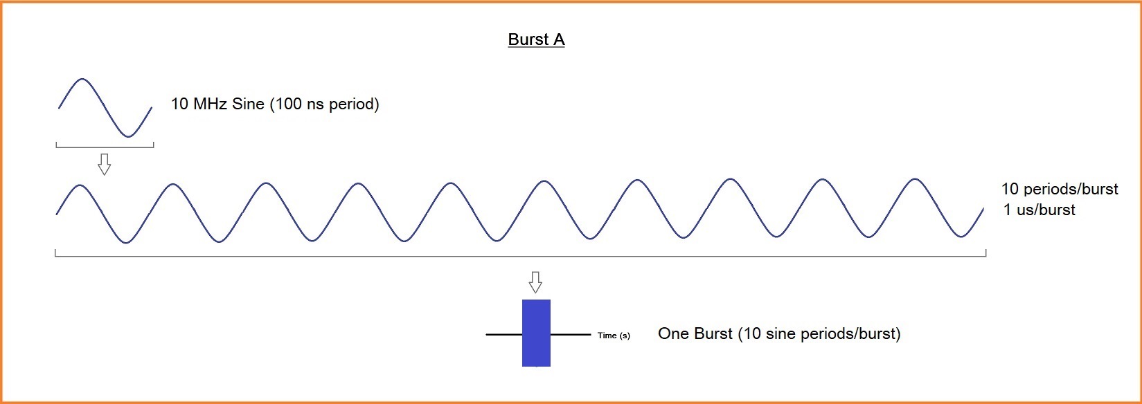
Let’s call this Burst A.
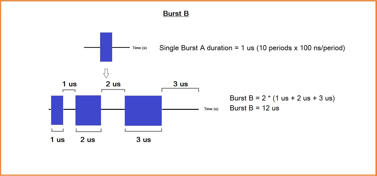
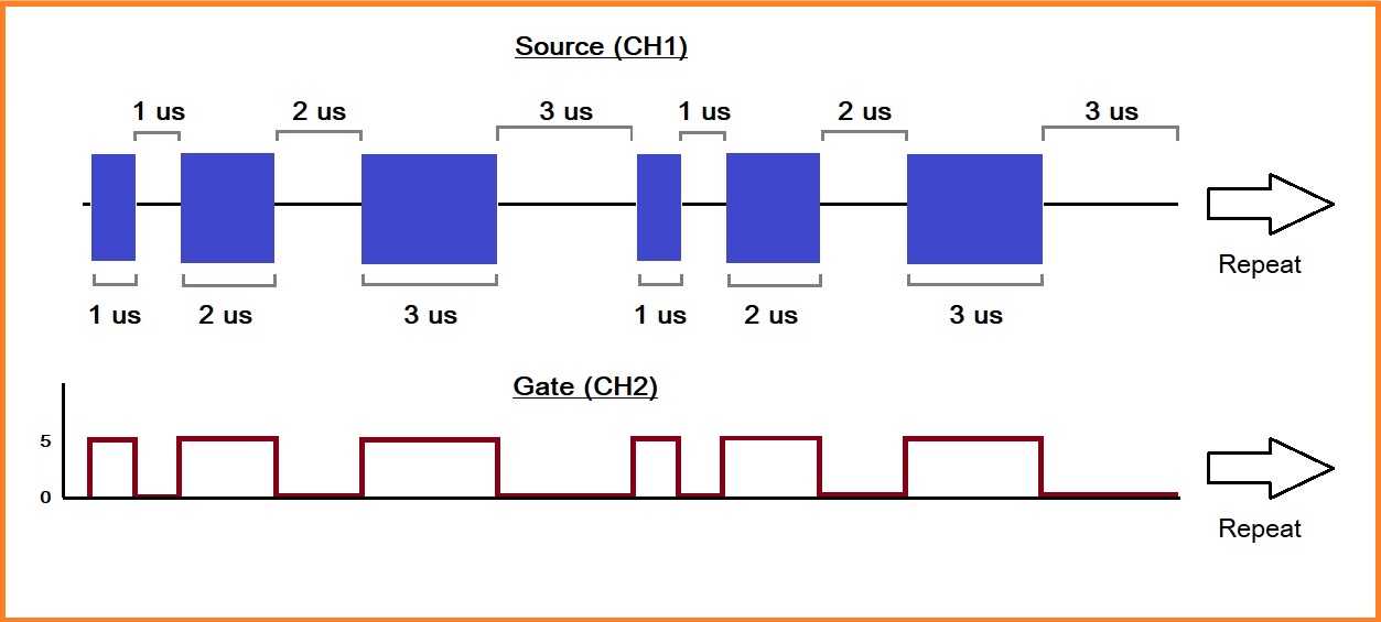
Then, let’s deliver a single burst (1 us duration, per Burst A specifications above), dwell for 1 us, deliver two bursts (2 us), dwell for 2 us, deliver three bursts (3 us), dwell for 3 us, and repeat.
Let’s sketch this up and label it Burst B.
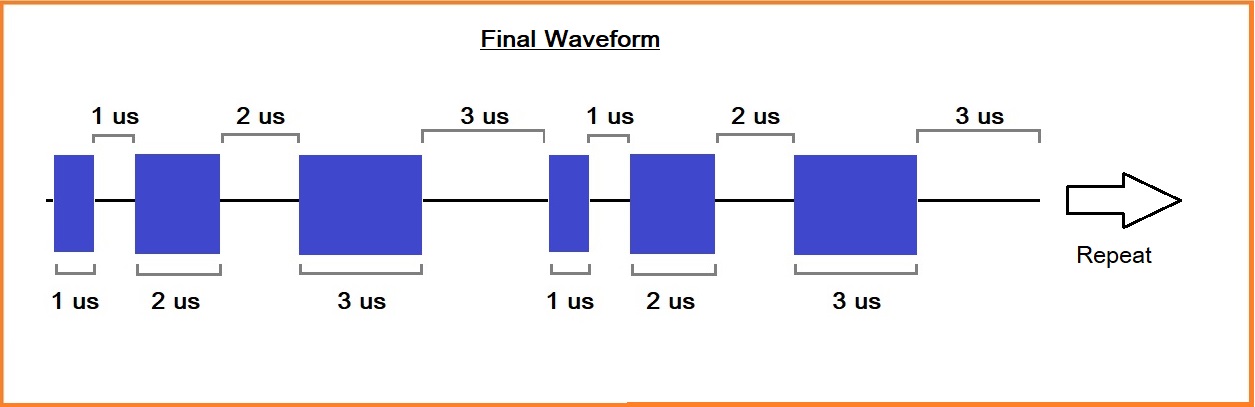
We will then deliver Burst B repeatedly until we decide to stop the test:
Gated Bursts
Now that we have our waveform diagram complete, including the duration of each step, we can start to work with the function generator.
As mentioned previously, we are going to use a gated burst to source the signal.
A gated burst sources an output for a period of time determined by the input voltage value to the gate input. Much like a valve on a pipe: When the valve is open, water flows. When the valve is closed, no water flows. Gated bursts work in a similar way. When the gate is “open”, the output signal will “pass through”. When the gate is “closed”, no signal will be present.
So, we will need a “gate” signal that follows our burst output requirements. So, on for 1 us, off for 1 us, on for 2 us, off for 2 us, on for 3 us, and off for 3 us. If we sketch that out, we can clearly see that we need a square wave pulse train with variable on and off times:
Instrument Setup
Here, we will use the SIGLENT SDG1032X function generator. Channel 1 will source our sine wave and have a gated burst control on the output. We then configure Channel 2 to control the gate.
CH1 Setup:
– Sine wave (Press Waveforms > select Sine)
– 20 Vpp (Press Parameter > Amplitude > enter 20 and select Vpp)
– 10 MHz (Press Parameter > Frequency > enter 10 and select MHz)
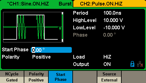
– Set Gated Burst mode, External Source, Positive Polarity (Press Burst > Set Gated > Polarity Positive > Source Internal)
Here is parameter/burst screen for CH1:
CH2 Setup:
For this application, we don’t have a standard waveform that can deliver the output that we require. So, we will have to build an arbitrary waveform with the following qualities:
- 0 – 5 V, dwell at 5 V for 1 us
- 0 V for 1 us
- 0 – 5 V, dwell at 5 V for 2 us
- 0 V for 2 us
- 0 – 5 V, dwell at 5 V for 3 us
- 0 V for 3 us
This can be seen in the figure below:
There are a few different techniques for building this arbitrary waveform. For this application, I am choosing to use SIGLENT EasyWave software to draw the waveform.
For more information on how to build a waveform using Coordinate Mode with EasyWave, click here:
https://siglentna.com/operating-tip/coordinate-mode-with-easywave/
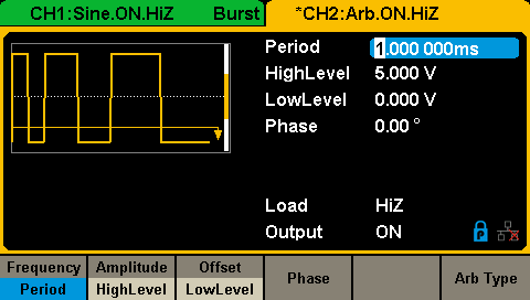
Here is the setup screen for CH2 after creating the waveform:
– Now, we need to connect the Channel 2 output (our gate control signal) to the gate input.
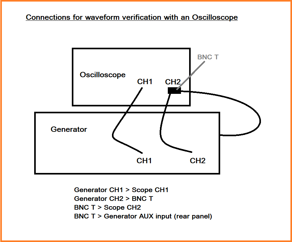
- Connect CH2 output to the Aux input on the rear panel of the SDG using a 50 Ohm BNC coaxial cable (Here I connected a BNC “T” and another cable to an oscilloscope so that I could capture the gate signal (Ch2) and the output (Ch1):
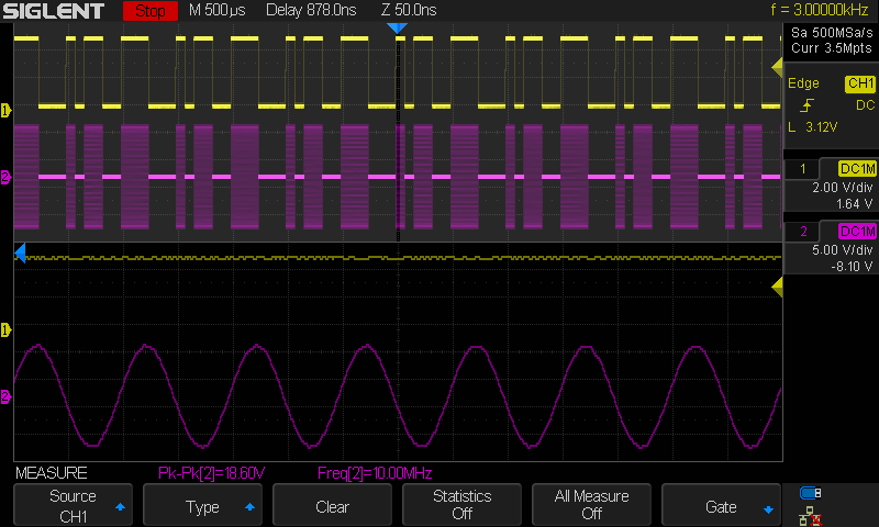
Verify with an oscilloscope before connecting to your device-under-test (DUT):
The yellow trace is the output from the generator CH2 (Gate control signal) and pink is the gated burst output from CH1: